Let Unified Theory Inc. of Camarillo, CA help you with your next Industrial Process, Mechanical, Structural or Electrical project.
Our team of engineers can handle almost any industrial process system design.
Whether your project is for conveyor controls, emission controls, exhaust systems, air handling systems, fluid systems, materials handling systems or high speed manufacturing, UTI can handle it all.

Engineering Consultants in Southern California

WELCOME TO THE UNIFIED THEORY, INC. (UTI) BLOG


We serve Industrial Clients with Engineering and Architectural Resources, Processing and Facility Needs.


Save Time
Save Money
Access Industry Experts


UTI offers a full range of industrial and commercial architectural services, including project management, construction management and training.

Wednesday, August 27, 2008

Industrial Ventilation - Dilution Ventilation

Dilution ventilation is usually accomplished with the use of large exhaust fans in the walls or roof of a building or room. Opening doors or windows can be used as dilution ventilation, but this is not always a reliable method since air movement is not controlled. Cooling fans (floor fans) are also sometimes used as a method of ventilation, but these fans usually just blow the contaminant around the work area without effectively controlling it.

Dilution ventilation can be more effective if the exhaust fan is located close to exposed workers and the makeup air is located behind the worker so that contaminated air is drawn away from the worker's breathing zone. See Figure 1 for examples of best locations for exhaust fans and air inlets.


In cases where the source of contamination is widely scattered or is from a mobile source, like carbon monoxide from a forklift, large wall or roof exhaust fans can be effective. Makeup air to replace the air exhausted is necessary for the best control. Simple openings in walls or doors can be sources of makeup air, or a second fan can draw makeup air into the building or room. However, makeup air may require heating in the winter resulting in increased heating bills.

Tuesday, January 22, 2008

PLC / HMI Programming California

Programmable Logic Controller (PLC) Program Development & System Design

  • PLC programming service for various PLC vendors including Allen-Bradley ( A-B ), Modicon, Seimens.
  • HMI screen development.
  • Documented ladder logic and HMI programs.
  • Modular programming methods use to help make fault finding easy.
  • PID control programming.
  • Industrial network communication design and implementation such as Ethernet, ControlNet, DeviceNet, DH+, Modbus Plus.

Unified Theory, Inc. 1320 Flynn Road, Suite 201, Camarillo, CA 93012

Ph: 805-389-7420 Fax: 805-389-7418  www.utieng.com        


Monday, January 21, 2008

VOC emission control using an Thermal

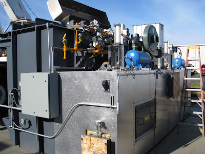
Regenerative Thermal Oxidizers – RTOs are used to capture and eliminate VOCs from an air stream.


Thermal treatment of VOC's and other air pollutants works by a simple reaction of the harmful air pollutants with oxygen and heat. In this environment the VOC's are converted to CO2, water vapor (H2O), and usable heat. These harmless by-products are released to atmosphere or use an energy recovery technique to further lower the operational costs.

UTI and its personnel have years of VOC's experience and have developed, through years of experience, process strategies and system configurations:

  • Solvent Handling, including VOCs Emission Reductions and Recovery
  • Odor Control through various technologies: Scrubbers, Carbon Adsorption, Bio Technology and Thermal Oxidation
  • Thermal Oxidation Systems ranging in size from 2,000 cfm to 250,000 cfm
  • Solvent Recovery Systems ranging in size from 5,000 cfm to 25,000 cfm
  • Bio Technologies up to 30,000 cfm
  • Incident Investigation of Failed Systems
  • Improved VOC Capture Efficiency for Process Systems
  • Provided the Design and Specification for VOC's Emission Reduction Equipment and Systems
  • Developed Standard CAD Details for VOC's Emission Reduction Systems
  • Redesigned Stack and Source Dampers in Conjunction with VOC's Emissions Reduction Equipment to Improve Process Optimization, Comply with MACT Standards and Reduce Energy Costs
  • Optimized Thermal Oxidation Systems
  • Specified Solvent Recovery Coil Replacements
  • Provided Financial Analysis for VOC's Emission Reduction Systems to Provide the Most Cost Effective System for given Applications
  • Provided Incident Investigation for Misapplied VOC's Emission Reduction Systems and Equipment Failures
  • Provided Expert Witness for Failed VOC's Emission Reduction Systems
  • Provided Solvent Extraction Systems Engineering Design
  • Designed Solvent Handling, Storage and Unloading Facilities
  • Designed Inline Moisture Process Control Systems
  • Developed Pulp & Paper Plant P&ID Drawings for Hazardous Systems
  • Created Process Flow Drawings & Mass Balance Tables
  • Designed Tether (Life Line) Certification
  • Provided Calendaring Roll Design and Consultation
  • Design Overhead Material Handling Systems and Hoist Certification
  • Engineered Polyester Fiber Handling System
  • Created Trim/Weed Conveying System
  • Provided Ammonia Engine Room Redesign and Certification
  • Designed Sewer System Design
  • Construction Management for Chemical Plants, Food Plants and Greenfield Facilities
  • Designed Furnace Gas Train Evaluation and Design
  • Provided Gas Train Design and Specifications
  • Designed and Developed Laminator and Sputter Platform Equipment
  • Provided Engineering for an Automotive Plant Expansion

Basic PLC system concept

A PLC system comprises of Input and Output modules that allow information to be monitored and to be controlled.

PLC Control System

Typical Input and Output modules for any PLC control system are:

  • Digital Inputs
  • Digital Outputs
  • Analog Inputs
  • Analog Outputs


There are also many specialty modules available for the more expensive systems such as:

  • High speed input modules
  • HART interface modules
  • Hydraulic control modules
  • Controlnet Interface modules
  • Devicenet Interface modules


Unified Theory, Inc. 1320 Flynn Road, Suite 201, Camarillo, CA 93012

Ph: 805-389-7420 Fax: 805-389-7418

E-Mail: thowsham@utieng.com Web: www.utieng.com        


Using a Programmable Logic Controller (PLC) to make your machine design go smoothly


Nothing takes the fun out of machine design more than thinking about how to control it in real time. Even small machine control applications require a lot of specifying, purchasing, and design.

Enter the PLC - Programmable Logic Controller. The concept of a PLC system is to help replace as many relays and wiring as possible in a control system. By doing this, the control of the system becomes more flexible. It is more practical to use a PLC based control system for any automation system as it will allow designers and end users alike, more control over the final operation of any machine. Real world examples of this are:


  • Adding time delays on to Inputs from Limit switches and Proximity switches
  • The ability to “filter” an analog process value. This ability has the effect of smoothing out the peaks and troughs of an analog signal so that machine control can be implemented without reacting to quick process value changes.
  • Easy implementation of PID control loops. Most PLC’s have some form of PID control built in to them. It is quite an easy process to add or modify an PID control to PLC logic. PID control is used in applications such as, but not limited to: Robotics, temperature control, pressure control, speed control, air flow control, humidity control, feed rate control and position control.
  • Easy access to live data within the automation system. These days, everyone from the operators on the factory floor to the CEO of the company wants information about machine operation in some form. PLC systems can help immensely in this arena. A majority of PLC controllers these days can be accessed via some form of network communication system. The most common form of this is Ethernet communications. Ethernet gives the ability to allow a local screen to show an operator some machine information that they need (E-Stop status, Door status, position status, Temperatures, Pressures, Run time, etc.)


Unified Theory, Inc. 1320 Flynn Road, Suite 201, Camarillo, CA 93012

Ph: 805-389-7420 Fax: 805-389-7418

E-Mail: thowsham@utieng.com Web: www.utieng.com        


Tuesday, January 15, 2008

Solvent-borne and Water-borne coatings

The VOC emissions from paper, film, and foil coatings occur during coating
application/flash-off and drying/curing of the coatings. Some of the VOC in the coatings evaporates from the web into the coating application area during coating application. Additional VOC evaporates from the web in the flash-off area (prior to entering the dryer). The majority, usually greater than 90 percent, of the VOC in the coatings volatilizes in the drying ovens. The VOC that evaporates from the web in the drying oven(s) are vented through an exhaust stack. The amount of VOC emitted varies depending on the type of coatings being used.

Traditionally, conventional solvent-based coatings (which generally have higher VOC content), have been used in the paper, film, and foil surface coating industry. Due to increased regulation at the federal and State level, the industry has steadily moved toward alternative coating formulations that reduce the amount of air emissions per unit amount of coating solids used. The types of coatings used in the paper, film, and foil surface coating industry include solvent-borne, waterborne, hot-melt adhesives and other 100 percent solids coatings, reactive, and radiation-cure coatings.

Solvent-borne coatings are widely used in the paper, film, and foil surface coating industry. The solvent content of the coating is highly variable in solvent-borne coatings, and depends primarily on the type of coating applicator used (e.g., reverse roll coaters require the use of coatings with lower viscosities than knife coaters, therefore could require a higher solvent content). For solvent-borne coatings, coating formulations typically range from 40 to 80 percent solvents by weight, as supplied by the manufacturer. Users may dilute solvent-borne coatings
with additional solvents. Solvent-borne coatings are typically applied at 60 to 90 percent solvent by weight and sometimes higher. The primary solvents in solvent-borne coatings include methanol, toluene, xylene, methyl ethyl ketone, acetone, ethyl acetate, and ethanol. Knife coaters, reverse roll coaters, and gravure coaters are commonly used to apply solvent-borne coatings.

Waterborne coatings contain water as a significant part of the fluid, although some organic solvents may be used at up to 30 percent of the fluid. Most coating equipment used for solvent-borne coatings can also be used for waterborne coatings. Knife coaters and gravure coaters are particularly well suited to application of waterborne coatings. However, troughs or trays may have to be mixed more often when they contain waterborne coatings than when they contain solvent-borne coatings because waterborne coatings are more susceptible to coagulation or agglomeration of their solids.


Monday, January 14, 2008

Description of VOC Emissions

The paper, film, and foil surface coating process can be described as a web coating
process, which is a process that applies a continuous layer of coating material across essentially the entire width or any portion of the width of a web substrate to: (1) provide a covering, finish, or functional or protective layer to a substrate; (2) saturate a substrate for lamination; or (3) to provide adhesion between two substrates for lamination. The web coating operations and emission control techniques do not vary significantly among the sectors of the paper, film, and foil surface coating industry.

A typical coating line consists of a series of one or more unwind/feed stations; one or more coating applicators; the flash-off area (the area between two or more consecutive coating applicators or between the coating applicator and the drying oven); one or more drying ovens; and one or more rewind/cutting stations.

There are several different types of coating applicators that may be used to apply coatings. The most common types of applicators include: rotogravure, reverse roll, slot die, knife, flexography, Mayer rod, dip and squeeze, and extrusion/calendering. The type of coating applicator used may differ among coating application stations in the same coating line.

Sources of VOC Emissions

The paper, film and foil coatings product category listed under section 183(e) of the CAA includes coatings that are applied to paper, film, or foil surfaces in the manufacturing of several major product types for the following industry sectors: pressure sensitive tape and labels (including fabric coated for use in pressure sensitive tapes and labels); photographic film; industrial and decorative laminates; abrasive products (including fabric coated for use in abrasive products) and flexible packaging (including coating of non-woven polymer substrates for use in flexible packaging). The category also includes coatings applied during miscellaneous coating operations for several products including: corrugated and solid fiber boxes; die-cut paper paperboard, and cardboard; converted paper and paperboard not elsewhere classified; folding paperboard boxes, including sanitary boxes; manifold business forms and related products; plastic asceptic packaging; and carbon paper and inked ribbons.

Coating performed on or in-line with any offset lithographic, screen, letterpress, flexographic, rotogravure, or digital printing press is not part of the paper, film and foil coating category. In addition, size presses and on-machine coaters that function as part of an in-line papermaking system are not part of the paper, film, and foil coating category. The application of inks, coatings and adhesives on or in-line with rotogravure or flexographic printing presses used in the production of flexible packaging is addressed in the CTG for Flexible Package Printing (EPA 453/R-06-003, September 2006). The application of inks, coatings and adhesives on or inline with publication rotogravure printing presses is addressed in the CTG for Graphic Arts: Rotogravure and Flexography (EPA 450/2-78-033). The application of inks, coatings and adhesives on or in-line with offset lithographic or letterpress printing presses is addressed in the CTG for Offset Lithographic Printing and Letterpress Printing (EPA 453/R-06-002, September
2006).